3.LCD Cable customization
LCD screen cables are generally connected in two ways:
- Solution 1: the FPC is bonded directly to the LCD, and the customer uses a matching connector to connect with the display.
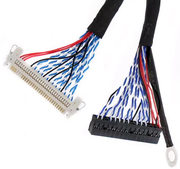
- Solution 2: the LCD module retains a connector, while an FPC cable, FFC cable or wire harness carries the signal to the motherboard.
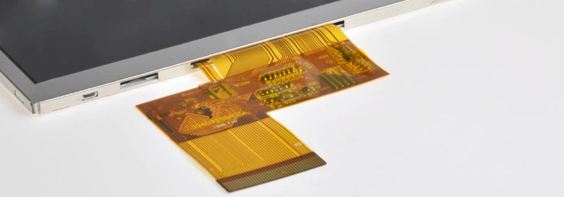
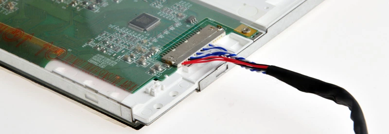
The direct-FPC route keeps the product compact and is often suitable for handheld or space-limited products. The connector-and-cable route is better when the motherboard and display are separated, when the transmission distance is longer or when vibration resistance is important.
DISEA supports engineering evaluation for both connection methods.
FPC:
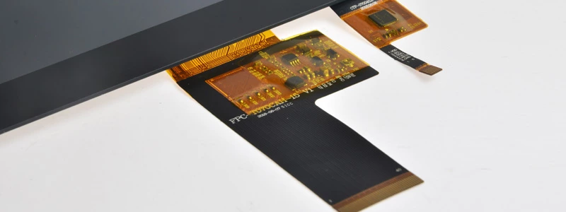
FPC shape, length, pin definition and pin pitch can be customized to match different mechanical layouts and interface requirements. Electromagnetic shielding film can also be used when improved EMI immunity is required.
The FPC circuit can be optimized through filtering, anti-interference design, layout adjustment and impedance matching to improve signal stability for different application environments.
Cable:
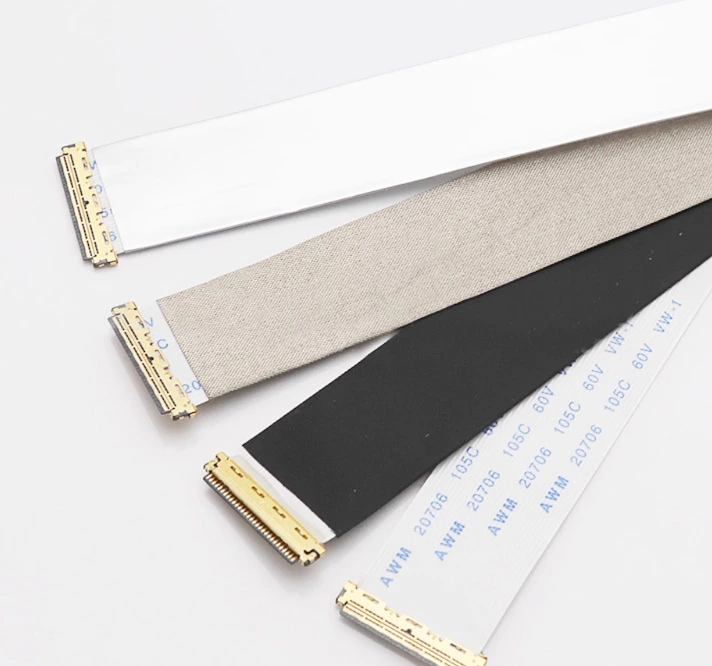
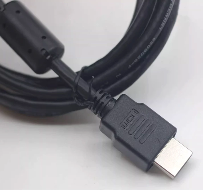
Cable length, material and connector type can be adapted to match different interface requirements. When signal quality needs additional protection, shielding, grounding or a magnetic ring can be added.
Combining multiple interfaces:
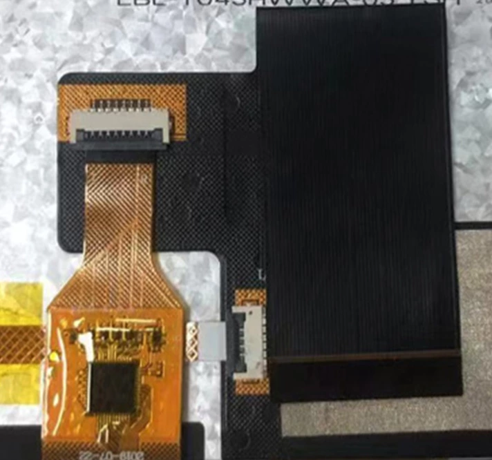
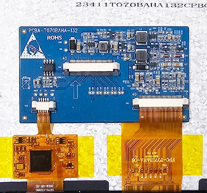
An LCD module with touch functionality can include several interfaces. Combining the LCD and CTP interfaces can save connector space on a compact motherboard and simplify assembly.
The LCD and CTP should normally avoid sharing the same VDD because power interference may occur. Backlight, LCD, RTP and CTP signals can also be integrated on one TCON PCB when the project requires it.
Signal conversion:
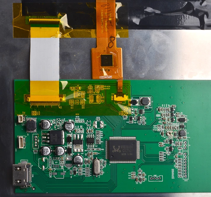
When the native LCD interface does not match the motherboard, a conversion solution can be used. For example, an RGB display can be adapted to an MCU interface, and other interface combinations can be reviewed according to the selected screen and system board.
For greater stability, the conversion circuit is normally placed on a PCB. This increases the overall product thickness, so the mechanical dimensions should be evaluated in advance.
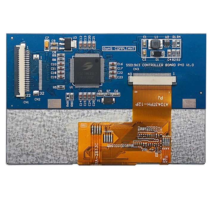
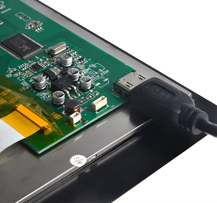
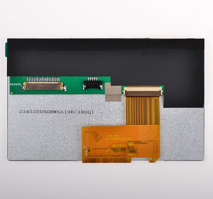
The images show customized project examples. Only partial product views are presented to protect customer and product information.
3 Technical Experts And 70+ Project Engineers Will Assist You
Share the target interface, cable type, length, connector, pin definition, signal-conversion need and installation distance for an engineering review.
Send Message