What Must Be Specified for a Custom Industrial PCAP Panel?
A custom PCAP panel is selected as a sensor, cover lens, controller, firmware and host-interface combination. Size alone does not establish whether it will work through the required gloves, reject water or remain stable beside the equipment's electrical noise sources.
DISEA's G+G touch-panel customization starts with the cover drawing and installation conditions. Confirm the viewing area, overall outline, glass thickness, mounting, printed border and FPC route before approving a sensor layout. Review the cover-glass options alongside the touch design.
| Decision | Provide with the RFQ | Confirm before sample approval |
|---|---|---|
| Cover lens and sensor | Drawing revision, thickness, viewing area, border and mounting | Approved sensor/cover stack, FPC routing and connector drawing |
| Glove operation | Actual glove samples, material, thickness and required gestures | Touch response and false-touch behavior with the final cover lens |
| Water and cleaning | Wet fingers, spray, droplets, standing water and cleaning conditions | Which inputs remain enabled, when lockout is acceptable and how touch recovers |
| Host interface | I2C or USB requirement, host hardware, OS and available power | Pinout, voltage, protocol, driver support and power-up sequence |
| Electrical environment | Power supplies, motors, radios, grounding and EMC/ESD targets | Touch performance in the installed system, with test method and acceptance limits recorded |
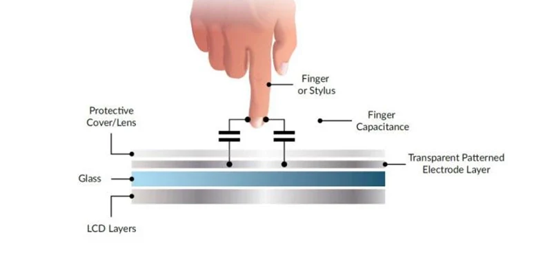
Choose the Touch Controller Around the Installed Equipment
The controller must support the selected sensor, cover stack and required input modes. EETI describes glove input and noise-immunity features in its PCAP controller overview; availability of a feature does not qualify a particular DISEA assembly for your application.
Check touch behavior while the host power supply, motors, radios and nearby electronics are operating. Missed touches, position errors and unintended activation should be assessed using the final enclosure, grounding and cable layout, not only an isolated touch sample.
For a long production program, request the proposed controller part number, firmware revision, supplier lifecycle information and change-notification process. Do not assume a fixed ten-year supply period or that no future redesign will be required.
EMC and ESD: Define a Test Requirement, Not a Generic Rating
A controller feature list is not a compliance report for the complete product. Agree the applicable standard, test setup and acceptable touch behavior with the engineering team and test laboratory.
| Review area | Required test context | Evidence to request |
|---|---|---|
| Conducted and radiated immunity | Applicable method, levels, frequency range, cabling and operating mode | Results for the proposed touch stack and host configuration |
| ESD | Contact/air discharge points, test levels, grounding and recovery criteria | Recorded false-touch, interruption and recovery behavior |
| Emissions | Applicable product standard, enclosure, host electronics and cable layout | System-level test report for the configuration being released |
Interfaces
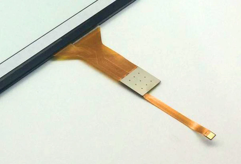
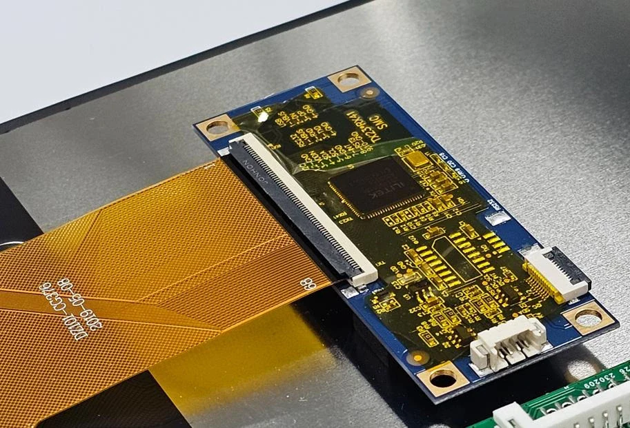
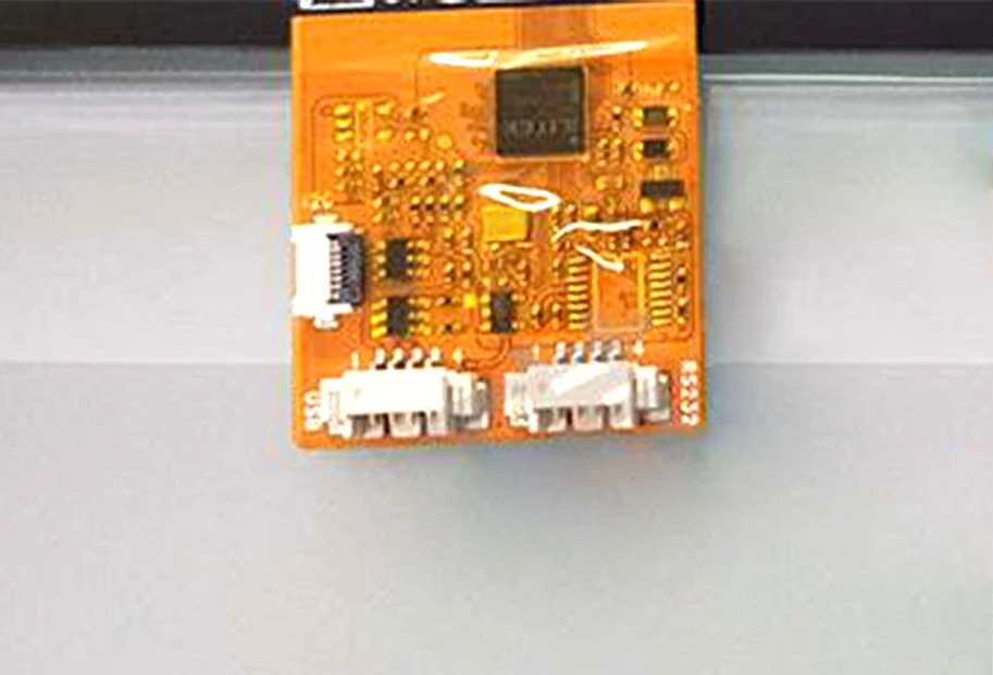
DISEA reviews I2C and USB touch-controller options against the host system. For I2C, confirm logic levels, address, interrupt/reset signals, bus timing and the host driver. For USB, confirm the device protocol and support in the target OS image. Dual-interface examples are shown below; the required combination must be confirmed for the selected controller and assembly.
PCAP Water Resistance
Water rejection is not an enclosure waterproof rating. A touch controller's wet-touch behavior and the finished product's sealing are separate requirements. The illustrations below explain conditions to test; they are not qualification results for every DISEA touch panel.
1. Water and Touch Performance
Liquids or conductive materials can affect mutual capacitance signal and make touch performance unstable.
Distinguish wet-finger operation from water on the sensor surface. Record the liquid, coverage, panel angle and required gestures when comparing samples.
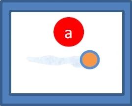

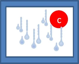


| NO. | Condition | What to Evaluate |
|---|---|---|
| a | Wet Finger | Check tracking accuracy, sensitivity and jitter with the intended input method. |
| b | Sprayed / Moisture | Check position accuracy and unintended activation as moisture coverage changes. |
| c | Water Drips | Check unintended activation and tracking interruptions when gestures cross moving droplets. |
| d | Pouring | Record which gestures remain usable and whether the controller enters a restricted-input mode. |
| e | Puddles | Check unintended commands, any required input lockout and recovery after water is removed. |
2. Controller Modes Under Wet Conditions
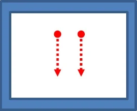
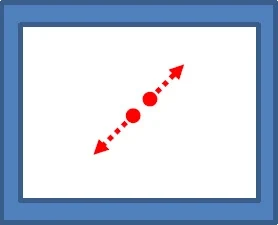
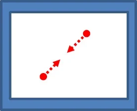
The existing EETI EXC80H/EXC82H reference diagram illustrates wet-condition mode switching. A controller configuration may retain a limited set of inputs or disable touch when water interference is detected. Confirm the behavior and supported firmware options for the controller actually proposed for your project.
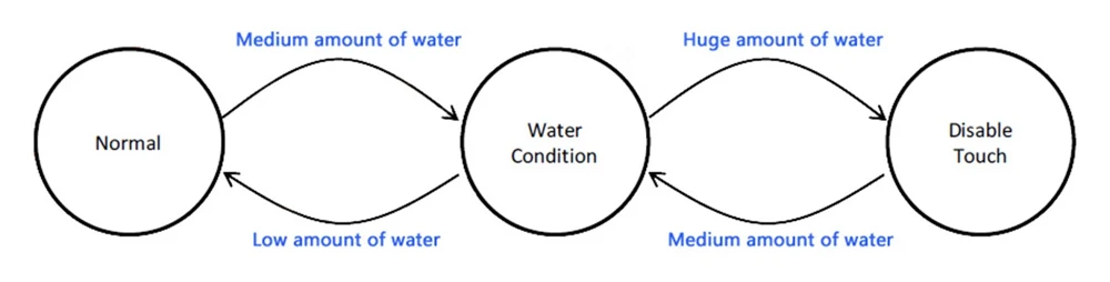
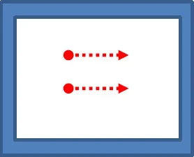
Single-touch operation, two-finger gestures and lockout/recovery behavior are separate acceptance items. The gesture illustrations show what to discuss with the controller supplier; do not assume every gesture remains available in every wet condition.

3. Build a Wet-Touch Validation Matrix
Use the final sensor, cover lens, firmware, mounting angle and host electronics. Specify the liquid and its concentration where relevant. The following table is a test-planning checklist, not measured performance data.
| Condition | Define before testing | Record on the sample |
|---|---|---|
| Wet finger | Input method, wetting condition and target positions | Detection, tracking accuracy and unintended activation |
| Spray or moisture | Surface coverage, exposure and installation angle | Missed touches, jitter and behavior near the border |
| Moving droplets | Droplet path and required drag or gesture operation | False touches and breaks while crossing wet areas |
| Pouring or standing water | Which controls must remain usable and whether lockout is acceptable | Enabled input modes, unintended commands and recovery |
| Cleaning and drying | Cleaning method and acceptable recovery time | Behavior during wiping and after water is removed |
Evaluate gloves and water together. Conductive liquids and increased sensitivity can change false-touch behavior. Agree measurable acceptance criteria for the actual liquid, glove and cover stack instead of applying a generic "normal" or "waterproof" label.
4. System Design Considerations for Wet Operation
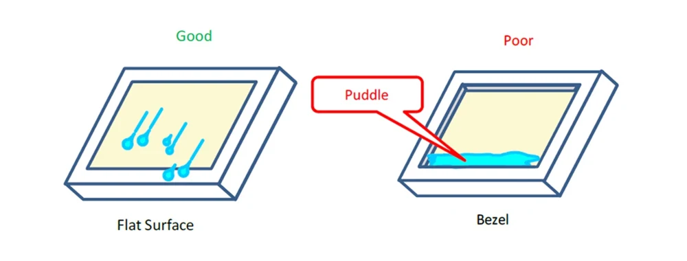
Review drainage, borders, coatings and the user interface with the final mechanical design. These design considerations do not replace sample validation:
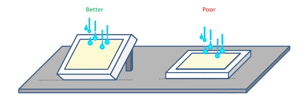
a. Review surface shape and mounting angle so water can drain instead of collecting around the active area.
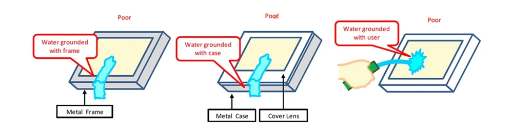
b. Review conductive borders and grounding. Water connecting the sensor area, enclosure or user can change the detected signal, so include the final bezel and frame in testing.
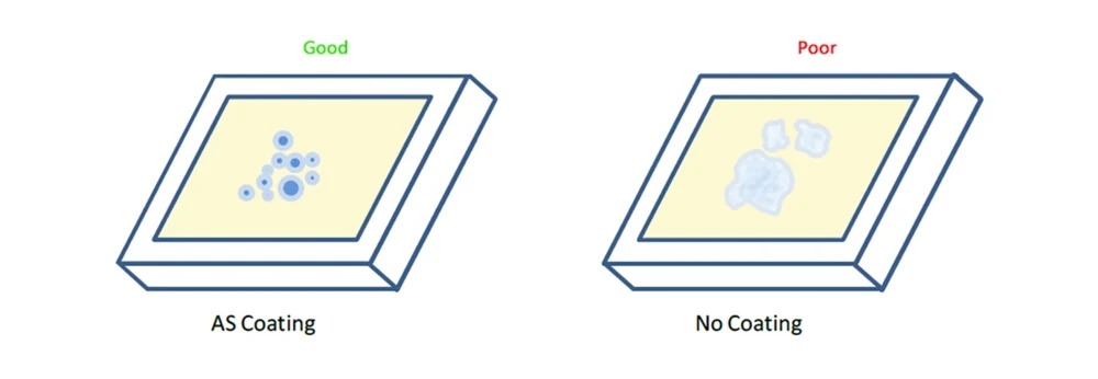
c. Evaluate the proposed cover-surface coating and its effect on wetting and drainage. Confirm performance with the actual glass and cleaning method rather than assuming a coating eliminates water interference.
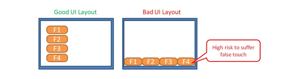
d. Include edge controls in the touch test plan. Review control placement and the equipment's response to unintended input, particularly where water can collect near the border.
Glove Touch and Cover-Lens Validation
Glove support is not a universal yes/no property of PCAP. Send the actual gloves, including material and thickness, together with the cover-lens drawing and required gestures. Evaluate dry and wet operation if both occur in the application.
Gloves can reduce the detected touch signal. Sensitivity tuning may improve detection but can also change noise and water response. Record signal margin, missed touches and unintended activation with the selected controller and firmware; use that supplier's current application guidance to set thresholds.
The illustrations below identify example glove samples from the existing reference material. Their thicknesses describe the samples, not a supported glove or cover-glass limit for a DISEA product. Confirm the complete glove/cover/sensor combination by testing.
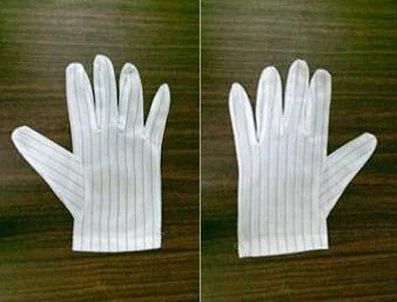
Material: Nylon
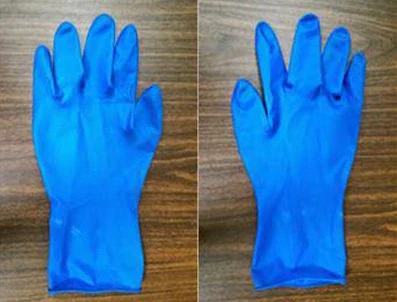
Material: Rubber
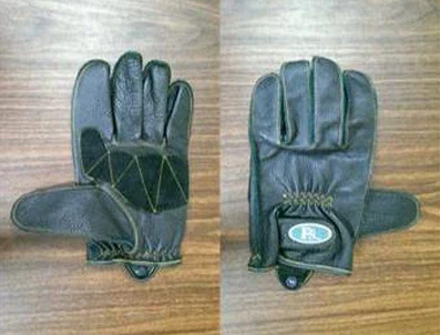
Material: Leather
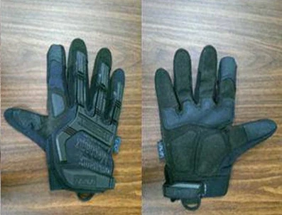
Material: Synthetic leather
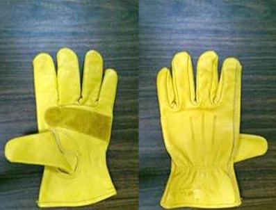
Material: Leather
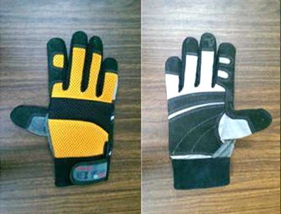
Material: Synthetic leather
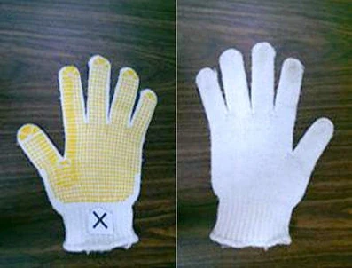
Material: Cotton
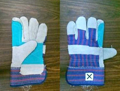
Material: Suede
Technical References and Project Evidence
The existing controller diagrams and glove illustrations are based on EETI reference material. For current product-family information, see EETI Projected Capacitive Touch Products and its industrial and outdoor touch overview. These overviews do not certify a DISEA assembly or establish its test limits.
Before sample approval, request the selected controller's current application note, sensor/cover drawing, firmware revision and project-specific validation record. DISEA Micro is the engineering website operated by DISEA Electronics Co., Limited.
Content updated: .
Prepare Your PCAP Engineering Review
Send the cover drawing, viewing area, host interface, glove samples, wet-use conditions, EMC/ESD targets and expected production timeline. These inputs help define the proposed assembly and the evidence needed for sample approval.
Send Message