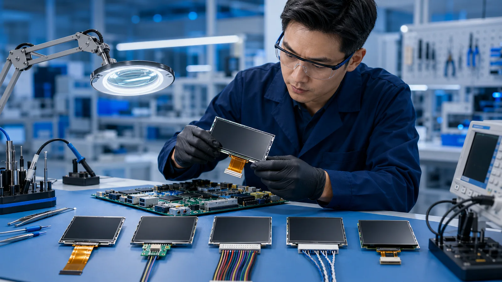
Which TFT LCD interface should I choose?
Start with the display output your host processor actually provides. Compare that output with the module interface, resolution, color depth and frame rate, then confirm the pinout, initialization and timing. SPI, MCU, RGB and MIPI describe different integration routes; a connector that fits mechanically does not establish electrical compatibility.
Compare published module interfaces and use the controlled datasheet to validate the shortlist.
A TFT LCD interface connects the host processor or controller board to the display timing electronics. The choice affects PCB routing, connector size, software work, achievable frame rate, electromagnetic compatibility and the amount of display data the host must generate.
Before selecting a module, confirm whether the host provides a display controller, only a serial peripheral port, or a dedicated high-speed display output. Then compare the module resolution and refresh requirement with the available bandwidth. DISEA's TFT LCD interface engineering page provides the related customization routes.
SPI: low pin count for compact displays
SPI is common on small TFT LCD modules because it uses relatively few signal lines and is supported by many microcontrollers. The display controller normally includes display RAM, so the host sends commands and pixel data rather than continuous raw timing signals.
SPI works well when the resolution is modest, the user interface changes are limited, and a compact connector is important. Full-screen animation at larger resolutions can expose bandwidth limits, so estimate the real update rate before finalizing the hardware.
MCU parallel: more pins, higher practical throughput
An 8080- or 6800-style MCU interface transfers commands and pixel data over a parallel bus. Compared with SPI, it can improve update speed but uses more pins and PCB space. It is useful when the host microcontroller does not provide RGB timing but the application needs faster screen updates.
RGB: direct pixel timing from the host
RGB interfaces carry pixel data together with synchronization and clock signals. The host must continuously generate the display timing, which usually means using a processor or microcontroller with an LCD controller. RGB is common in embedded HMIs where the host can drive the panel directly and software frameworks need a frame buffer.
Confirm data width, pixel clock, porch timing, voltage levels and color mapping. An 18-bit or 24-bit RGB label alone does not guarantee compatibility.
LVDS: differential transmission for larger displays
LVDS sends high-speed data over differential pairs and is widely used where parallel RGB routing would require too many conductors or create signal-integrity concerns. It is common on larger industrial and automotive-style panels. Check channel mapping, bit mapping, connector pinout, cable impedance and panel timing.
MIPI DSI: high-speed serial display connection
MIPI DSI is common in compact, high-resolution devices where the processor has a compatible DSI host. Integration requires matching lane count, lane speed, command/video mode, initialization sequence and panel timing. A mechanical fit does not imply that an existing DSI host configuration can initialize a different module.
Interface selection checklist
- List the display outputs available on the host processor or controller board.
- Confirm resolution, color depth, target frame rate and whether full-screen animation is required.
- Check whether display RAM is inside the module controller or must be supplied by the host frame buffer.
- Match logic voltage, signal timing, initialization commands and connector pinout.
- Review FPC length, cable routing, grounding and EMI constraints.
- Allow software time for drivers, rotation, color order and power sequencing.
Examples from the current catalog
| Model | Published interface | Resolution | Confirm before integration |
|---|---|---|---|
| DS-T009HESA-01 | 4-SPI, 13 pin | 80 × 160 | ST7735S initialization and pin assignment |
| DS-T0177SSI-02 | 8-bit MCU, 20 pin | 128 × 160 | ILI9163V timing and logic levels |
| DS-T015BOSA-01 | 1-lane MIPI, 14 pin | 320 × 320 | Compatible host, lane configuration and initialization |
| DS-T021BCSA-02 | 24-bit RGB, 40 pin | 480 × 480 | Host display timing and FPC pinout |
These are published model configurations, not promises of plug-and-play compatibility. Open the linked model page and request the current datasheet, timing and controlled drawing before sample approval. Other interface requirements can be reviewed through the ODM process.
Send the processor model, available interface, target resolution, frame rate and current schematic or connector definition.
Request an engineering review