ENVIRONMENTAL REQUIREMENTSOperating rangeStart-up, steady-state and storage conditions Assembly stackLCD, backlight, touch, adhesive and cover lens EnvironmentCondensation, sunlight and enclosure heat ValidationApplication-specific test requirements
Wide Temperature TFT LCD Displays for Industrial & Outdoor Equipment
A wide operating-temperature target affects the LCD mode, backlight, touch sensor, adhesive stack, cover lens and validation plan. DISEA reviews the complete display assembly against the real equipment environment rather than treating temperature as a single line item. For a -30 to 85 °C operating requirement, DS-T035HLSWA-01 is a published 3.5-inch starting point. Compare its operating and storage limits in the model specification table; confirm the complete assembly before sample approval.
BUYER CHECKLIST
Temperature Requirements to Include in the RFQ
A useful RFQ connects the display specification to the host electronics, enclosure and real operating condition.
- Minimum and maximum operating temperature at the display location
- Storage temperature and cold-start expectations
- Indoor, outdoor, vehicle-cabin or sealed-enclosure installation
- Humidity, condensation, vibration and sunlight exposure
- Touch technology and cover-lens bonding materials
- Brightness, duty cycle and internal heat generated by the product
TEMPERATURE SELECTION
How to Specify a Wide Temperature TFT LCD
A wide-temperature display should be evaluated as a complete assembly. The LCD cell, backlight, polarizers, adhesives, touch stack and enclosure may have different environmental limits.
| Condition | What to Define | What DISEA Reviews |
|---|---|---|
| Cold start | Minimum start-up temperature and acceptable response time | LCD response, backlight start-up, touch behavior and power sequence |
| High-temperature operation | Maximum internal temperature, duty cycle and sunlight exposure | Image stability, backlight heat, polarizer and adhesive suitability |
| Storage and transport | Non-operating extremes, duration and packaging environment | Material limits, condensation risk and recovery after storage |
| Touch and cover lens | PCAP or RTP, bonding method, glove and water requirements | Sensor, optical adhesive, cover glass and controller compatibility |
| Enclosure | Sealing, ventilation, mounting and heat sources near the display | Actual display temperature, stress, cable routing and validation plan |
The required operating range must be confirmed for the complete touch-display assembly; it should not be inferred from one component datasheet.
TYPICAL APPLICATIONS
Where This Display Requirement Is Common
Use the installation scenario to define validation conditions. These are engineering review examples, not customer case studies or application certifications.
Outdoor controllers
Specify cold start and the temperature at the display behind its cover lens in direct sunlight. Check readability, backlight power and enclosure heat together; outdoor air temperature alone is not the module's operating condition.
Industrial automation
Define the internal temperature of the control cabinet with nearby electronics running. Review display duty cycle, ventilation, mounting stress and touch behavior at the expected steady operating temperature.
Cold-storage equipment
State the minimum start-up temperature and acceptable time for the image and touch to become usable. Include transitions between cold and warm areas so that condensation and recovery are part of the test plan.
Vehicle and mobility systems
Separate unpowered storage conditions from powered use in the cabin or enclosure. Review vibration, mounting, FPC routing and thermal cycling; an industrial module is not automatically automotive-qualified.
Energy equipment
For a sealed outdoor control box, define heat from the host electronics, continuous operating hours and solar exposure. Review the LCD, adhesives, backlight and touch stack at the resulting internal temperature.
Field measurement devices
Specify intermittent start-up, battery operation, gloves and transitions between indoor and outdoor use. Test response, visibility and touch on the complete handheld assembly rather than the LCD cell alone.
PUBLISHED MODEL DATA
Compare Published Operating and Storage Temperatures
The values below come from each linked DISEA product page. They are module specifications, not test results for a custom touch-display assembly or an endorsement for every application above.
| Model and specification source | Size / resolution | Operating temperature | Storage temperature | Published configuration |
|---|---|---|---|---|
| DS-T035HLSWA-01 | 3.5 inch / 320 x 240 | -30 to 85 °C | -30 to 85 °C | IPS, RGB 24-bit, 54 pin; no touch panel |
| DS-T027BOIA-01 | 2.7 inch / 320 x 320 | -20 to 70 °C | -30 to 80 °C | IPS square, RGB 16-bit, 40 pin; no touch panel |
| DS-T024BQSA-01 | 2.4 inch / 240 x 320 | -20 to 70 °C | -30 to 80 °C | IPS, RGB/MCU/SPI, 45 pin; no touch panel |
Operating and storage ranges are not interchangeable. A storage limit does not establish that the display can start or operate at that temperature. All three listed modules have no touch panel; adding PCAP, RTP, adhesive or a cover lens requires a separate assembly review. A -20 to 70 °C module does not meet a -30 to 85 °C operating requirement on the basis of its published specification.
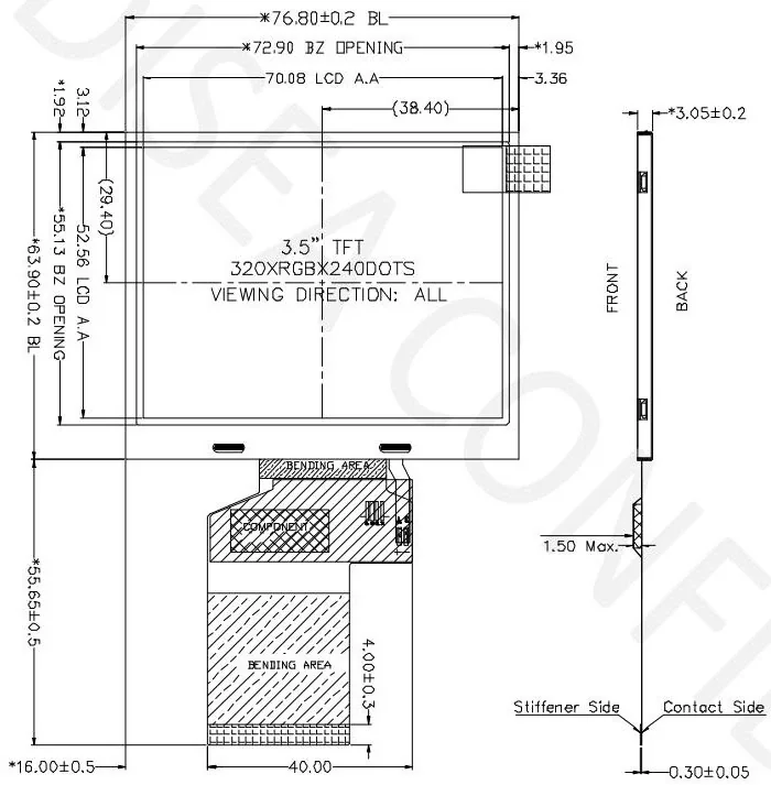
For a -30 to 85 °C operating target, DS-T035HLSWA-01 is a published starting point when its size, resolution, interface and outline fit the design. Review its mechanical drawing and request the current controlled specification before sample approval. For other sizes and interfaces, compare the published module table.
VALIDATION EVIDENCE
What Should a Temperature Test Record Include?
Define the acceptance criteria before testing. A quoted operating range alone does not describe image response, cold-start time or the result for the complete installed assembly.
- Configuration: exact module, drawing revision, touch/cover stack, host electronics and enclosure.
- Conditions: temperature measurement location, start-up and steady-state targets, humidity, dwell time and any cycling profile.
- Operating mode: backlight setting, duty cycle, power sequence and the image or touch pattern used.
- Acceptance: image stability, usable response time, touch behavior, mechanical condition and recovery after exposure.
- Traceability: sample identifiers, test date, method, results and any exceptions that require review.
ENGINEERING FAQ
Questions from Product and Procurement Teams
Does the LCD temperature range apply to the complete touch display?
Not automatically. The touch sensor, adhesives, cover lens, backlight and connector system also need to be checked against the required environment.
Why is the enclosure drawing useful?
The enclosure affects heat flow, mounting stress, FPC routing, sealing and the actual temperature seen by the display.
Can a standard module be used for a wide-temperature project?
Possibly. The correct route depends on the required range and whether the complete assembly meets the environmental and lifecycle requirements.
TEMPERATURE SPECIFICATION
Wide Temperature LCD Display Operating Range Review
A Wide Temperature LCD Display must be assessed at cold start, steady high temperature and thermal transition—not only by quoting a range. If the RFQ calls for a -30 to 85°C TFT LCD, confirm that the LCD cell, backlight, FPC, adhesive, touch stack and connector are all reviewed for the installed conditions.
B2B RFQ
Prepare an RFQSend the Target Specification for Review
Include size, resolution, interface, mechanical limits, brightness, touch, environment, sample quantity, annual forecast and target timing.
ENGINEERING GUIDE
Review Cold Start, Heat and Material Reliability Together
Use the wide-temperature guide to connect LCD response, backlight heat, polarizers, adhesives, touch and enclosure conditions.
Model data source: the individual product pages linked in the comparison above. Confirm the current drawing and specification with DISEA before release. Content updated: .