Which LCD driver board matches your display?
Match the board's input to the host output and its output to the exact LCD model, interface, timing, pinout and backlight circuit. A screen diagonal or connector shape alone cannot establish compatibility. A module's driver IC, a TCON and an external HDMI controller board perform different jobs.
Start with the compatibility checklist, compare published module interfaces, or send the LCD datasheet and host details for review.
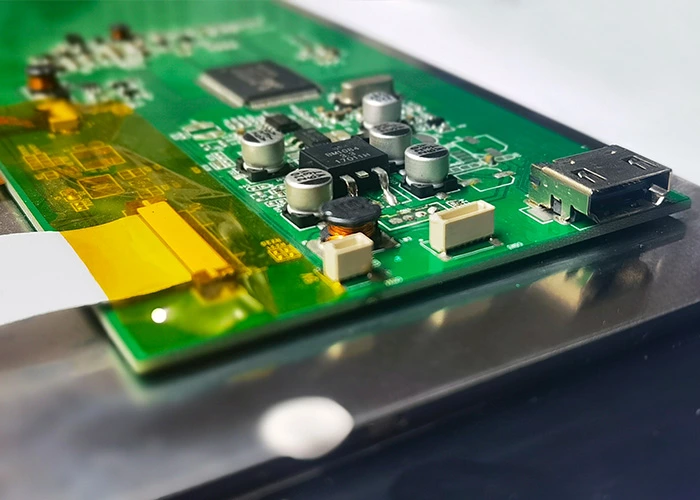
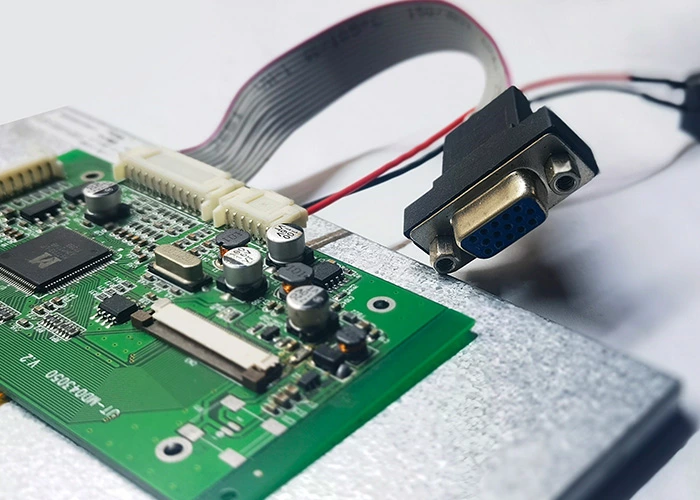
Industrial display projects are often controlled by platforms such as Raspberry Pi or Windows-based computers. These platforms commonly use HDMI or VGA, while the original LCD module normally does not accept HDMI directly. An added driver board converts the host signal into the format required by the LCD module.
HDMI/VGA:
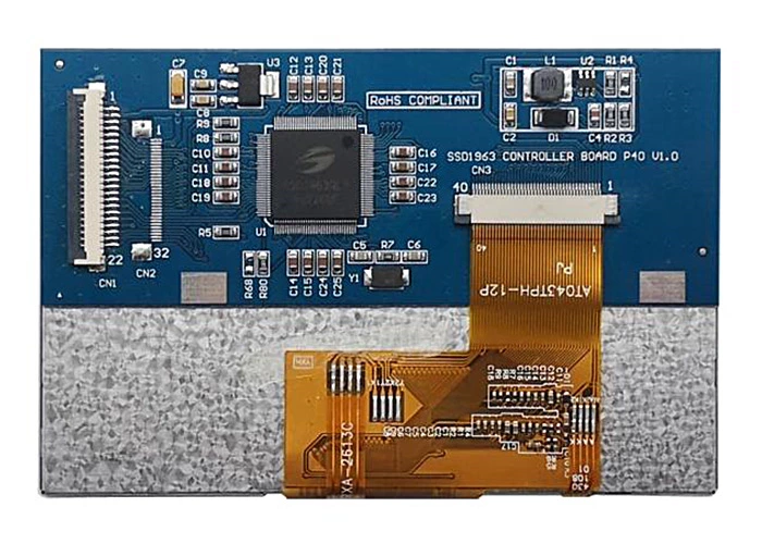
DISEA Micro reviews controller-board compatibility around the exact TFT LCD model rather than screen size alone. Compact modules may use native SPI, MCU, RGB or MIPI, while common 4.3-inch, 5.0-inch, 7.0-inch and 10.1-inch displays can also be matched with available or customized HDMI/VGA controller boards when the host output does not directly match the selected display.
SPI:
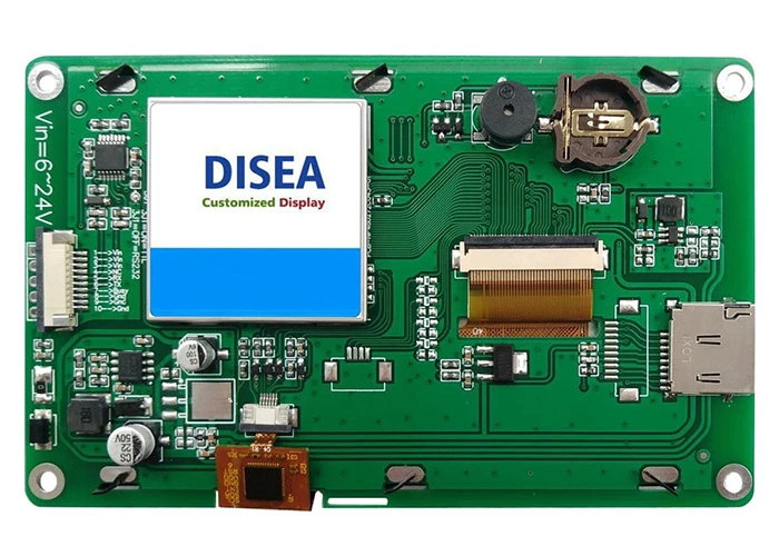
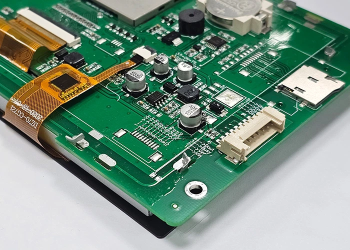
Some embedded platforms provide only SPI even when the selected resolution or user-interface workload needs faster updates. This can include 4.3-inch, 5.0-inch or 7.0-inch displays that are not practical to refresh through native SPI alone. SPI bandwidth must be checked against resolution, color depth and frame rate; a controller with display memory can reduce host workload, but the architecture must be verified with the exact module and application.
MCU:
An existing microcontroller platform may require an MCU-style bus even when the selected LCD controller uses another native interface. For example, 4.3-inch or 5.0-inch displays may need an FPC- or controller-PCB-based conversion circuit when the original LCD driver IC does not support MCU directly. Bandwidth, memory, initialization and production cost are reviewed against the option of selecting a directly compatible TFT LCD module.
TCON:
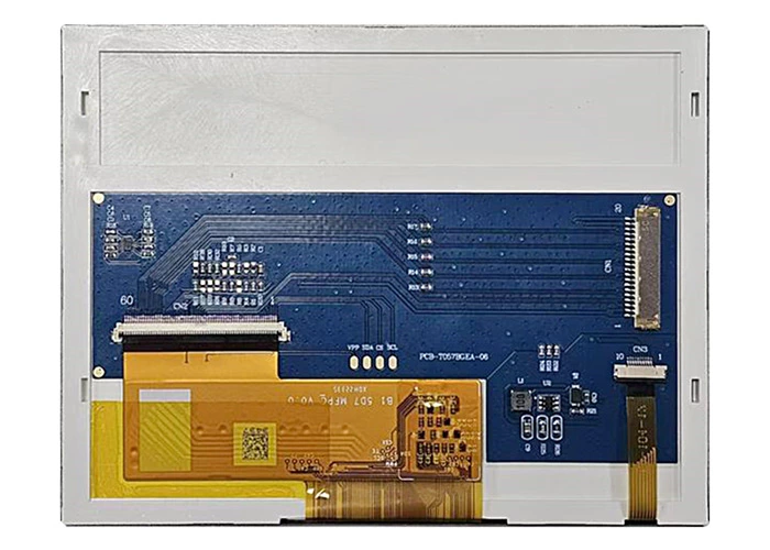
The TCON board—also called a logic board—receives data signals from the customer’s motherboard, processes them through its logic circuitry and converts them into the timing and drive signals required by the LCD display.
LCD Display Driver IC vs TCON vs Controller Board
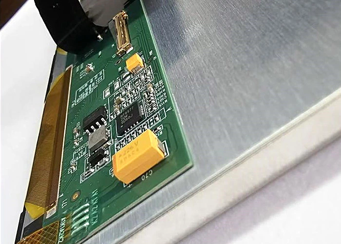
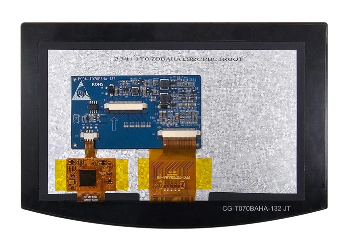
Searches for an LCD display driver can refer to three different components. Identify the required level before selecting hardware or requesting a custom board.
| Component | Primary Function | When It Is Selected |
|---|---|---|
| LCD driver IC | Controls source, gate or module-level pixel driving and initialization | Usually selected as part of the LCD module architecture |
| TCON or logic board | Generates panel timing and maps incoming display data | Used when the panel requires dedicated timing conversion |
| LCD controller board | Converts HDMI, VGA, SPI, MCU, UART or another host signal | Used when the host interface does not directly match the TFT LCD |
DISEA reviews TFT LCD module and controller-board compatibility. Semiconductor driver IC selection must still follow the exact panel and controller architecture.
TFT Controller IC and Native Interface Examples
A controller IC inside a TFT LCD module is not the same as an external HDMI or signal-conversion board. These published modules show why the exact controller, interface and FPC must be checked together.
| Published Module | Controller | Native Interface | Selection Use |
|---|---|---|---|
| DS-T009HESA-01, 0.96 inch 80×160 | ST7735S | 4-wire SPI, 13 pin | Compact SPI host integration |
| DS-T0177SSS-01, 1.77 inch 128×160 | ST7735P | 3/4-wire SPI, 12 pin | Small TN module with native SPI |
| DS-T0177SSI-02, 1.77 inch 128×160 | ILI9163V | 8-bit MCU, 20 pin | Parallel MCU host connection |
| DS-T035BQSA-01, 3.5 inch 240×320 | ST7789V | RGB/MCU/SPI, 50 pin | Multiple native host-interface options |
Use the linked product page and current controlled drawing for the final electrical decision. The example table does not imply that one controller or external board can be substituted for another.
How to Choose a TFT LCD Driver Board
A compatible controller board must match both the host signal and the native electrical requirements of the TFT LCD. Screen size alone is not enough to select a board.
1. Confirm the Host Input
Identify what the main system actually outputs. A PC or single-board computer may provide HDMI or VGA. An embedded processor may expose RGB, LVDS, MIPI DSI, SPI, MCU, UART or RS232. The board must accept this host signal without adding unnecessary conversion stages.
- Host platform and operating system
- Available video or serial interface
- Required boot behavior and startup time
- Cable length and connector constraints
2. Match the Native LCD Output
The board output must match the display interface, resolution, pixel clock, timing, lane count, voltage and pin definition. Two modules with the same diagonal size can use different timings and connectors, so the LCD datasheet and mechanical drawing are required.
- RGB bit depth, sync mode and pixel clock
- LVDS channel count, mapping and voltage
- MIPI DSI lane count and initialization sequence
- SPI or MCU bus width and controller IC
3. Review Power, Backlight and Touch
Separate the LCD logic supply from the LED backlight requirement. Confirm input voltage, LED string voltage and current, dimming method, power-on sequence and thermal limits. If the assembly includes PCAP or RTP, define the touch-controller interface and cable routing at the same time.
- Logic voltage and board input supply
- Backlight driver current, PWM and brightness control
- I2C, USB or resistive-touch controller
- Standby, wake and power-sequence requirements
Information Required Before Board Selection
Send these items together to avoid choosing a board that powers the panel but cannot produce a stable image.
| Item | What to Confirm | Why It Matters |
|---|---|---|
| LCD model | Exact module part number and datasheet | Defines the controller IC, interface and electrical limits |
| Resolution & timing | Active pixels, refresh target, pixel clock and porch values | Prevents unstable images, wrong colors or no display |
| Native interface | RGB, LVDS, MIPI DSI, SPI or MCU details | Determines the required board output architecture |
| Host input | HDMI, VGA, RGB, LVDS, MIPI, SPI, UART or MCU | Determines whether signal conversion is required |
| Connector & pinout | Pitch, mating connector, pin definition and FPC direction | Confirms electrical and mechanical connection |
| Power & backlight | Logic voltage, LED current, dimming and power sequence | Protects the display and achieves the brightness target |
| Touch | PCAP/RTP controller, USB/I2C and operating-system support | Ensures touch and display work as one assembly |
| Mechanical limits | Board outline, mounting holes, cable exits and enclosure space | Prevents integration problems after electrical validation |
Common TFT LCD Controller Board Questions
Can any HDMI board drive an LCD with the same screen size?
No. The board firmware, output interface, timing, connector and backlight circuit must match the exact LCD module. Always verify the module part number and datasheet.
Is an LCD driver board the same as a TCON board?
The terms are sometimes used loosely. A signal-conversion board may accept HDMI or another host input, while a TCON processes timing and drive signals for the panel. The required architecture depends on the native module interface.
When is SPI unsuitable for a larger TFT LCD?
SPI bandwidth can limit frame rate at higher resolutions. A board with display memory or a graphics controller may reduce host workload, but the required update rate and user interface must be reviewed.
What files should be sent for a compatibility review?
Send the LCD datasheet and drawing, host-board interface details, target resolution and refresh rate, power supply, touch requirement, enclosure limits and any existing board reference.
If you have another interface or driver-board concept, share the idea with DISEA so the engineering team can discuss a practical solution.
Engineering Support for TFT LCD Controller-Board Compatibility
DISEA's engineering team includes specialists with extensive TFT LCD industry experience who can review interface conversion, PCB integration and driver-board requirements.
Send Message